Application Guide for High Performance Brushless Servo Systems
September 18, 2014
This updated handbook is a helpful guide outlining the design considerations, calculations and application of brushless servo sytems, including helpful engineering formulas and conversion tables.
Sizing and application guidelines
- Mechanical considerations
- Motion profile considerations
- Sinusoidal brushless motor specifications
- Electrical noise and its causes
- Filtering
- Grounding, shielding, and segregation
ElectroCraft Incorporated
Mechanical Considerations
Application guidelines for sinusoidal brushless servomotors and drive amplifiers
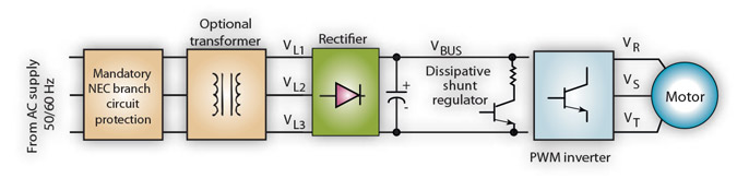
The trapezoidal or square wave current brushless servo is characterized the same as a brush-type servo drive and is generally well understood. The principles of sizing the sinusoidal brushless servo motor drive are similar, but there are some differences which merit review. Therefore, this section provides the guidelines for applying and sizing a servo drive using the sinusoidal brushless servo drive as an example. The basic structure of the servo system to be sized is illustrated in Figure 1.
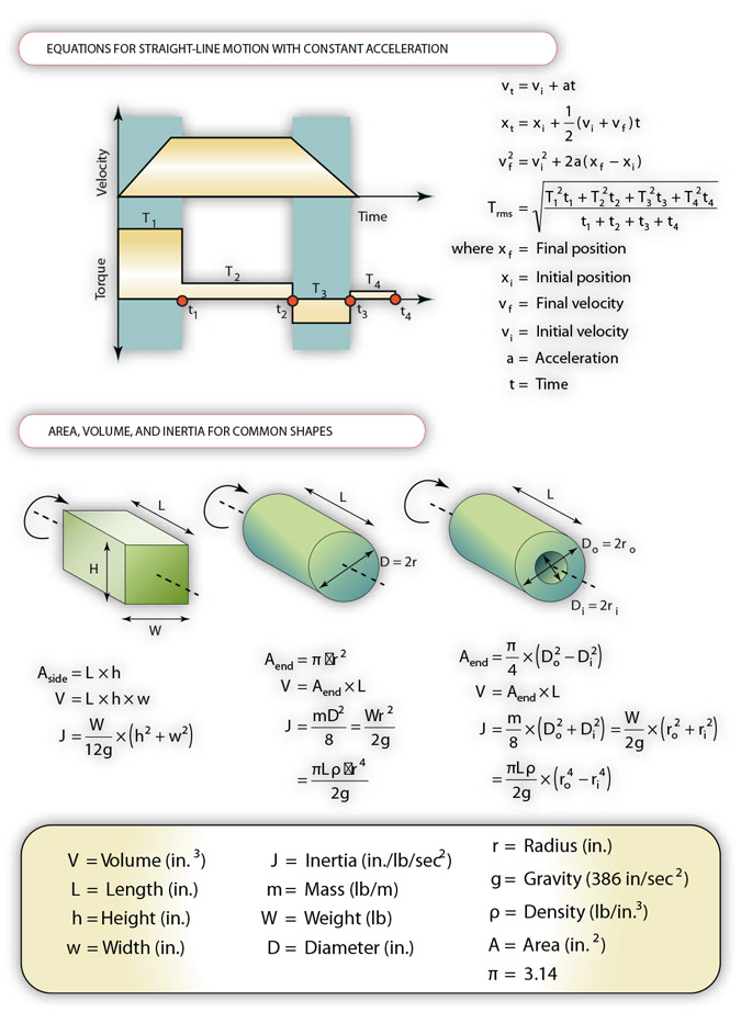
Many laborious calculations are made in the typical sizing process. Calculations include reflected load inertias, RMS and peak torques, average and peak currents, RMS maximum speeds, and so on.
Mechanical transmissions, gearing, and torsional resonances
The most commonly encountered mechanical transmissions can be analyzed for many applications and are shown in Figure 2. The choice of mechanical transmission is determined by application requirements. Useful equations in Figure 2 characterize the various transmission types. Another important decision is the choice of rotary gearing (if any) between the motor shaft and the mechanical transmission/load to be moved. There are many reasons for considering gear reduction in a motion control application such as:
Reducing inertial mismatch between motor and load.
Inertial mismatch should be minimized for high-performance applications, and is 1:1 for best results. Gearing reduces the reflected inertia by the square of the reduction ratio. For example, a 10:1 gear ratio reduces reflected load inertia by 10 squared or 100. However, do not fail to include the extra inertia of couplings, pulleys, or gears, as these can be significant and offset the inertia reduction. The addition of couplings or thin drive shafts will increase the compliance of the system as the motor winds up the transmission like a spring, this will result in resonances as the load moves and the spring is unwound. Also note that adding a gearbox will add backlash to the system, effectively removing the load from the motor within the backlash angle. This can lead to motor high frequency instability at standstill, causing excess motor heating and failure to accurately track contoured moves.
- High torque and low-speed applications. Most conventional brushless servomotors can operate at high speeds, such as 3,000 to 6,000 rpm. The torque increase due to the gear reduction (motor torque is multiplied by the gear ratio) is used to keep the motor physical size as small as possible. This is because the continuous torque rating (and not horsepower) determines the motor size and cost. Horsepower is equal to torque x speed. Therefore, for minimum motor size and inertia, motor speed should be as high as possible.
- Limited space. If there are space constraints, the use of gearing can allow a smaller overall package or it can allow the motor to be repositioned in a different localocation or orientation. Many different factors need to be taken into account when selecting gearing technology. The first step for a high-performance servo application is to determine which gearing technology best fits the application – by answering the following questions:
- What are the physical limitations for the application? For example, into what envelope must the motor/gearing fit, and must the motor be positioned at a right angle to the load? The three basic orientations are parallel, in-line, and right angle gearing.
- What reduction ratio is required? After deciding on the basic classification, the next factor to consider is the reduction ratio—illustrated in Figure 3 for the most common gearing technologies. For example, timing belts are generally not used for ratios above 3:1 while harmonic type gearing is usually not available with ratios below about 40:1.
At this point in the selection process, the performance parameters of the gearing technologies are examined to further narrow the choice. Figure 23 includes the most important performance parameters and their relative ranking. These are only approximate rankings and variations do exist.
For high-performance servo applications, three of the performance parameters are of particular importance and need additional explanation: accuracy, torquecarrying capability, and reliability.
Accuracy is often equated to backlash but there is more that must be considered. Backlash is the space between mating parts or gears and it is usually specified in degrees or arc minutes. Normally, gears need backlash to run reliably because space is needed to accommodate lubrication, manufacturing errors, and eccentricities in the gears and other components. The tradeoff is to keep the backlash as low as possible without sacrificing efficiency or other performance features. Excessive backlash can cause positioning error and instability so low-backlash gearing is generally preferred with brushless servo drives.
Other components of accuracy include stiffness (compliance), transmission error, and output smoothness. Stiffness is the amount of deflection measured when a load is applied to the reducer. Insufficient stiffness will result in positioning errors or torsional resonance problems. Transmission error is a measure of how accurately the motor input shaft position is translated through the reducer. Gear ratios are seldom exact and positional inaccuracies are also caused by gear imperfections. The torque and speed output must also be smooth and free from ripple if the input speed and torque is smooth and ripple-free. Eccentric-type reducers (such as harmonic or cycloidal gears) typically have output ripple under some operating conditions; timing belts and spur, bevel, planetary, or worm gearing are less susceptible to this characteristic.
The torque-carrying capability varies among the different types of reducers and is usually related to the frame size within any one type of technology. The objective is to ensure that the chosen reduction method has ample torque-carrying capability for the application. Some applications are light-duty and do not place heavy torque demands on the reducer. The torque-carrying capability of the reducer should have a 25 to 50% safety margin to ensure a long life.
Finally, reliability is primarily a function of the reducer component quality, efficiency, and the life expectancy for reducer type. For example, timing belts usually wear out faster than spur gears. Worm gears, due to their sliding gear action, also usually wear out faster than spur gears. Preloaded contact members, as found in harmonic and cycloidal gearing, wear out faster than the other forms of gearing. Timing belt gearing should only be of the HTD type to ensure high stiffness while V belt, non-HTD type timing belts, and chains should be avoided with high performance servo drives.
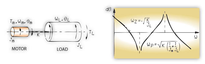
High performance servo drives typically are applied with highvelocity loop bandwidths. In practice, a torsional resonance exists due to mechanical compliance between the load inertia and the motor inertia. A model of this mechanical system and the open-loop frequency response is shown in Figure 4. The compliance is modeled as a torsional spring with its inertia and damping neglected. Best results are obtained if the torsional resonant frequency is kept as high as practical. Torsional stiffness K of a solid round shaft is proportional to the fourth power of the diameter and inversely proportional to the length. Therefore, torsional stiffness is dramatically improved by selecting a motor and other mechanical transmission element with the largest shaft diameter.
A common torsional problem is improper coupling of the motor to the load. A key-type coupling should be avoided if possible; a compression-type coupling that is clamped as close as possible to the motor flange is best. Axial shaft loading due to impact shocks as a result of hammering the coupling on the shaft is absolutely not allowed, as this can damage the motor bearings or break the encoder disc.
Finally, if some torsional resonance is unavoidable and is affecting the servo system performance, many suppliers can provide electronic damping schemes in the servo drives that help minimize the torsional resonance effect.
Motion Profile Considerations
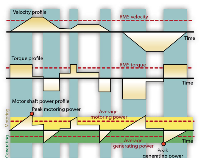
With the load defined, the worst-case velocity-time or velocity-distance profile (as in Figure 5) is analyzed to determine the following significant information:
- RMS and peak torque requirement of the motor
- RMS and maximum speed requirement of the motor
- Average and peak current requirement of the amplifier
- Average and peak motoring power
- Average and peak generating power
Arbitrary motion profiles can be defined and, along with the mechanical system information, are used to calculate the significant sizing information. Different mechanical parameters (such as gearing), motion profiles, and motor choices can be quickly and easily analyzed for the optimum selection of a motor/amplifier combination.
Sinusoidal Brushless Motor Specifications
ElectroCraft specifies the important motor constants for a three-phase sinusoidal back-EMF motor as:
Ke = line-to-line peak volts/KRPM
Kt = in-lb/peak phase amps
R = line-to-line resistance (Ohms)
L = line-to-line inductance (Henrys)
The peak value of the line-to-line voltage or phase amps is defined as the zero to peak value of the sine wave. For reference, the RMS value of a sine wave is the peak value divided by the square root of two. Also, Kt is related to Ke:
Kt = Ke/11.834 for a DC motor
Kt = Ke/13.662 for a sinusoidal current with a sinusoidal-EMF brushless motor.
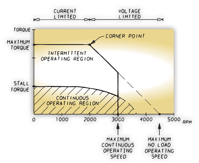
The torque-speed curve of a brushless servo system is shown in Figure 6. The continuous operating region is defined by operating the motor to the maximum allowable winding temperature at various speeds and recording the output torque. The continuous torque rating is worst case if the motor is in free air during the test. Electro- Craft brushless motors are normally rated mounted to an aluminum plate of a specified dimension. Notice that the continuous torque output of the motor decreases as the speed is increased. Eventually the continuous torque is reduced to zero, this occurs when the BEMF voltage and winding inductance limit the current to a level where the motor generated torque matches the motors internal drag torque from bearing friction and windage. The low-speed portion of the peak curve is usually limited by the amplifier peak current rating; available amplifier voltage usually limits the high-speed portion of the peak torque curve. As the speed increases, a voltage limit is reached which causes peak torque to roll off at higher speeds.
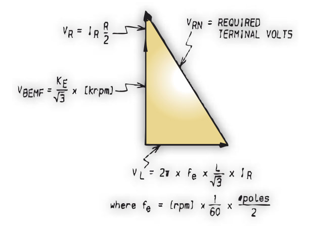
To better understand the torque-speed characteristics of the sinusoidal brushless motor, refer to the steady state per phase model shown in Figure 7. The voltage and current quantities are sinusoidal and are related as shown in Figure 8.
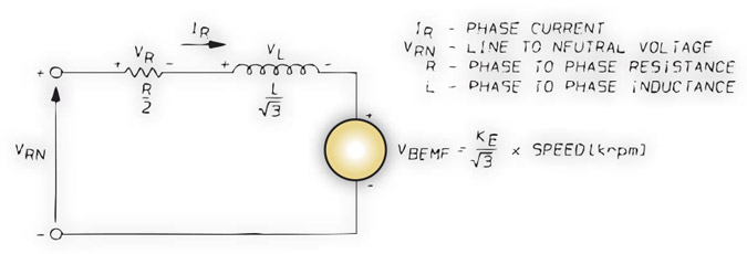
Notice how the voltage drop across the inductance begins to dominate as speed (or frequency) increases, which eventually causes the peak torque to roll off as mentioned before.
By knowing the maximum available line-to-neutral motor terminal volts, the peak torque characteristic as a function of speed can be calculated using the per phase motor model. The maximum line-to-neutral volts can be calculated using the following relationships. (Refer to Figure 8.)
Vbus [DC volts] =
2 x VVL1-L2 [volts RMS line-to-line]
Maximum VRN [peak volts] = Vbus/3
Once completing the work to calculate the motor and amplifier requirements, the torque-speed curves are used to select the proper ElectroCraft motor/amplifier combination.
The continous motor torque should be avaible at the RMS velocity of the motion profile. Some allowance should be made for motor Kt and Ke tolerance and for voltage drop due to low line conditions and transformer load regulation. Figure 5 shows the motoring and generating power for this incremental motion profile. Only the motoring power is supplied from the AC power line, as ElectroCraft servo drives do not regenerate power to the AC power line.
Actual AC power requirements are higher than the average motorshaft power due to power losses in the motor, drive, and transformer. A multiplication safety factor of about two is used to account for the losses and power factor. Many suppliers provide load regulation curves for their standard transformers; one such curve is shown in Figure 9.
In servo applications, the peak power requirements for good transformer voltage regulation usually require selection of a power transformer that is oversized for continuous power requirements. Conservatively sized motor/ amplifier operates longer without failure and reduces application problems that are caused by under sizing the motor/amplifier combination.
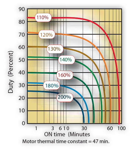
Up to now, it has been assumed that the motion profile cycle time is short compared to the motor thermal time constant. The motor thermal time constant is defined as the time to reach 63.2% of the rated temperature rise when rated current is supplied to the motor. The motor thermally averages the power losses and reaches a constant steady state temperature. Some applications apply power and remove power to the motor with cycle times that are similar to the motor thermal time constant. In these cases, the motor temperature will fluctuate up and down as the power is applied and removed. To properly size these applications, duty cycle curves can be provided for the motors as shown in Figure 10. For example, the operating point labeled A in Figure 10 allows the motor to repetitively produce 200% continuous torque for about 6 minutes and no torque for about 24 minutes. The amplifier has a very short thermal time constant compared to the motor so the amplifier must be oversized to handle the peak motor torque on a continuous basis in these types of overload applications.
Brushless amplifier dissipative shunt
The final consideration in sizing the amplifier concerns the dissipative shunt regulator shown in Figure 1. Braking the motor returns energy stored in the rotating mechanical mass to the amplifier power supply. Because the power supply is not able to regenerate this energy back to the AC input supply, the power supply capacitor is charged up beyond its normal level. If the excess braking energy is low, then the capacitor may be able to absorb the excess energy and simply return it to the motor during the next motoring period. However, if the excess energy is high, then a clamp circuit is used to limit the bus voltage to a safe level and to dissipate the excess energy as heat in a power resistor.
The shunt regulator is specified to handle a peak power and a continuous power. If the peak power is exceeded, then the clamp circuit will be unable to limit the voltage to a safe level and the amplifier turns off. In practice, if peak shunt power is being exceeded, check to see if the current limit can be lowered or if the deceleration time can be lengthened. Applications that frequently stop and start with high inertia and high speed should be studied closely to see if continuous shunt power is exceeded. Vertical applications with a gravity load (especially ones without any form of counterbalance) must be very carefully considered as to continuous shunt power.
ElectroCraft drives have the ability to add external shunt resistors that extend the continuous and peak shunt power of the system. Figure 5 shows the generating power for an incremental motion profile: Actual dissipated power is less than the regenerated motor shaft power due to motor losses, amplifier losses, and energy absorbed by the bus capacitor.
Electrical Noise Considerations
Perhaps no other subject discussed so far in this handbook is as misunderstood as electrical noise. Nothing strikes fear in the industrial equipment user more than being told by the drive vendor, "You have a noise problem." While the subject is complex and the theory can (and does) easily fill a book, this section provides some guidelines that can minimize noise problems.
The majority of installations exhibit no noise problems. However, filtering and shielding guidelines are countermeasures if problems arise. In contrast, grounding and bonding guidelines combined with good panel layout are simply good practices and should be followed in all installations.
There are two characteristics to electrical noise: the generation or emission of electromagnetic interference (EMI), and the response, or immunity to EMI. The degree to which a device emits no EMI, and is immune to EMI, is called the device's electromagnetic compatibility.
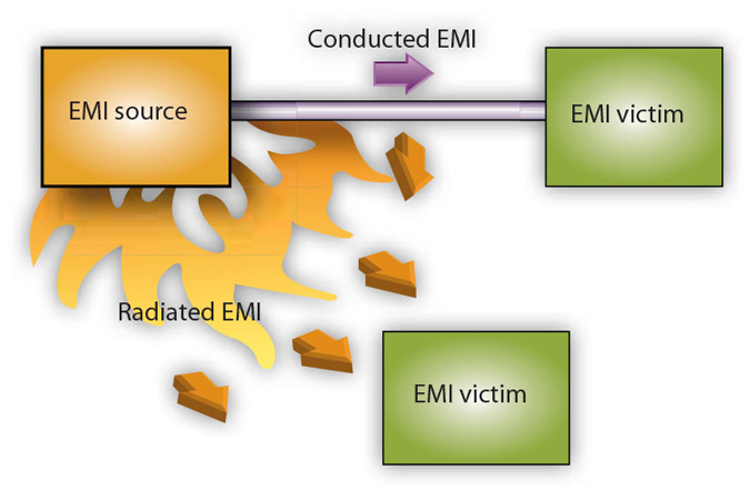
Figure 11 shows the commonly used EMI model. The model consists of an EMI source, a coupling mechanism, and an EMI victim. Devices such as servo drives and computers (which contain switching power supplies and microprocessors) are EMI sources. The mechanisms for the coupling of energy between the source and vicitm are conduction and radiation. Victim equipment can be and electormagnetic device that is adversely affected by the EMI coupled to it.
Equipment immunity is primarily determined by its design, but how one wires and grounds the device is also critical for EMI immunity. Therefore, selecting equipment designed and tested for industrial environments is paramount. Selecting equipment that is certified or designed to meet industrial immunity standards is a good start. Laying out the electrical panel in "Clean" and "Dirty" zones to segregate motor power wires from sensitive analog inputs etc. will cost very little in planning time compared to the cost of sending an engineer to site to find an intermittent EMI event.
Another tip: In industrial environments, use encoders with differential line driver outputs rather than single-ended outputs, and use digital inputs/outputs with electrical isolation, such as those provided with optocouplers.
Reconsider Figure 11. This EMI model provides only three options to eliminate the emission problem. The EMI source could be reduced, which in the case of servo drives would require slowing power semiconductor switching speeds. However, this degrades drive performance with respect to heat dissipation and speed/torque regulation.
Another possibility is to harden the victim equipment, which may not be possible or practical. The final and most realistic solution is to reduce the coupling mechanism between the source and victim – with filtering, shielding, and grounding.
Filtering
As mentioned, high-frequency energy can be coupled between circuits via radiation or conduction. The AC power wiring is one of the most important paths for both types of coupling mechanisms. The AC line can conduct noise into the drive from other devices, or can emit conducted noise directly into other devices. It can also act as an antenna and transmit or receive noise between the drive and other devices.
One method of improving the EMC characteristics of a drive is to use an isolation AC power transformer to feed the amplifier its input power. This minimizes inrush currents on power-up, and provides electrical isolation. In addition, it provides common mode filtering, though the effect is limited in frequency by the inter-winding capacitance.
Note: "Common mode" noise is present on all conductors referenced to ground while "differential mode" noise is present on one conductor referenced to another conductor.
An alternative is to use AC line filters to reduce the conducted EMI emitting from the drive. This allows nearby equipment to operate undisturbed. In most cases, an AC line filter is not required unless other sensitive circuits are powered off the same AC branch circuit. The basic operating principle is to minimize the high frequency power transfer through the filter.
An effective filter achieves this by using capacitors and inductors to mismatch the source impedance (AC line) and the load impedance (drive) at high frequencies The machine builder is responsible for the suitability of the filter selection in a specific application.
Selection of the proper filter is only the first step in reducing conducted emissions. Correct filter installation is crucial to achieving both EMI attenuation and to ensure safety. All of the following guidelines should be met for effective filter use.
- The filter should be mounted to a grounded conductive surface to establish a high frequency (HF) connection to that surface. To achieve the HF ground, the surface interface between the filter and structure must be free of paint or any other insulator. This may require paint removal from the inside of a cabinet. A wire should not be used to ground the filter because it will act as an antenna when ground currents are present.
- The filter must be mounted close to the drive input terminals. If the distance exceeds 1 ft, then a strap should be used to connect the drive and filter, rather than a wire.
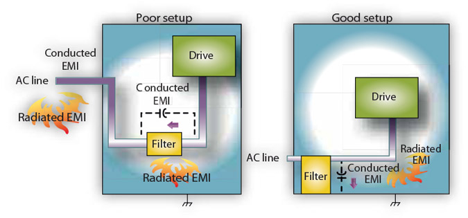
- The wires connecting the AC source to the filter should be shielded from, or at least separated from, the wires (or strap) connecting the drive to the filter. If the connections are not segregated from each other, then the EMI on the drive side of the filter can couple over to the source side of the filter, thereby reducing, or eliminating the filter effectiveness. The coupling mechanism can be radiation, or stray capacitance between the wires. The best method of achieving this is to mount the filter where the AC power enters the enclosure. Figure 12 shows a good installation and a poor installation.
When multiple power cables enter an enclosure, an unfiltered line can contaminate a filtered line external to the enclosure. Therefore all lines must be filtered to be effective. The situation is similar to a leaky boat. All the holes must be plugged in order to prevent sinking.
WARNING: The filter must be grounded for safety before applying power due to the leakage currents. Failure to properly ground the filter can be hazardous.
The only reasonable filtering at the drive output terminals is the use of inductance. (Capacitors would slow the output switching, and deteriorate the drive performance.) A common mode choke can be used to reduce the HF voltage at the drive output to reduce emission coupling through the drive back to the AC line. However, the motor cable stills carries a large HF voltage and current. In fact, motor cable length directly affects the amplitude and frequency of emissions on the AC line. Therefore, it is very important to segregate the motor cable from the AC power cable, or to use a shielded motor cable. For applications where long motor cables are required, the need for AC line filtering increases. More information in cable shielding and segregation is contained in the section on shielding.
Grounding, Shielding and Segregation
Grounding
High-frequency (HF) grounding is different from safety grounding. A long wire is sufficient for a safety ground, but is completely ineffective as a HF ground due to the wire inductance. As a rule of thumb, a wire has an inductance of 20 nH/in., regardless of diameter. At low frequencies it acts as constant impedance; at intermediate frequencies as an inductor; and at high frequencies as an antenna. The use of ground straps is a better alternative to wires. However, the length to width ratio must be 5:1 or better yet 3:1 to remain a good high frequency connection.
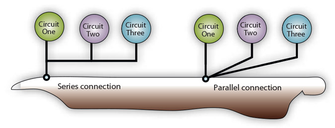
The ground system's primary purpose is to function as a return current path. It is commonly thought of as an equipotential circuit reference point, but different locations in a ground system may be at different potentials. This is due to the return current flowing through the ground systems finite impedance. In a sense, ground systems are the sewer systems of electronics and as such are sometimes neglected. The primary objective of a high frequency ground system is to provide a well definded path for HF currents, and mininimize the loop area of the HF currents paths. It is also important to separate HF grounds from sensitive circuits' grounds. A single-point parallel-connected ground system is recommended. Figure 13 shows single-point grounds for both series (daisy chain) and parallel (separate) connections.
A ground bus bar or plane should be used as the "single point" at which circuits are grounded. This minimizes common (ground) impedance noise coupling. This ground bus bar (GBB) should be connected to the AC ground, and if necessary, to the enclosure. All circuits or subsystems should be connected to the GBB by separate connections. These connections should be as short as possible, and straps should be used if possible. The motor ground conductor must return to the ground terminal on the drive, not to the GBB.
Shielding and segregation
The primary propagation route for EMI emissions from a drive is through cabling. The EMI radiating from the drive enclosure itself drops off very quickly with distance. The cables conduct the EMI to other devices, and can also reradiate the EMI. Therefore, cable segregation and shielding can be important to reducing emissions. Cable shielding can also increase the level of immunity of a drive.
The following suggestions are recommended for all installations, because they are inexpensive to implement.
Signal cables (encoder, serial, analog) should be routed away from the motor cable and power wiring. Separate steel conduit can be used to provide shielding between the signal and power wiring. Do not route signal and power wiring through common junctions or raceways.
Signal cables from other circuits should not pass within 1 ft of the drive.
The length of parallel runs between other circuit cables and the motor or power cable should be minimized. A rule of thumb is 1 ft of separation for each 30 ft of parallel run. The 1-ft separation can be reduced if the parallel run is less than 3 ft. Cable intersections should always occur at right angles to minimize magnetic coupling.
Do not route any cables connected to the drive directly over drive vent openings. Otherwise, the cables will pick up the higher levels of emissions that leaked through the vent slots. If you are constructing your own motor cable, a four-conductor cable should be used, with the four conductors twisted. The ground conductor must be attached to the motor and drive earth terminals.
The encoder mounted on the brushless servomotor should be connected to the amplifier with a cable using multiple twisted wire pairs and an overall cable shield. Otherwise noise on the encoder signals can cause drive faults in the drive.
If EMI problems persist, additional counter measures can be attempted. Here are several suggestions for system modifications.
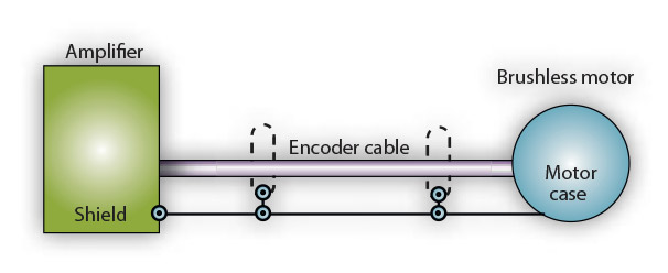
Placing a ferrite "donut" around a signal cable may help. The ferrite attenuates common mode noise but does nothing for differential mode noise. Connecting cable shields directly to the drive chassis instead of the cable connectors can reduce the effect of external EMI on the drive operation.
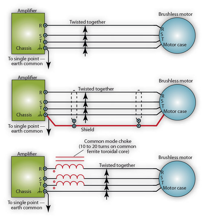
Use a shielded motor cable terminated at the circular section at both ends. The shield should be connected to the drive earth terminal, or chassis at the drive end, and the motor frame at the motor end. The coaxial configuration provides magnetic shielding, and the shield provides a return path for HF currents, which are capacitively coupled from the motor windings to the frame. If power frequency circulating currents are an issue, a 250-VAX capacitor should be used at one of the connections to block the 50/60 Hz currents, but pass the HF currents. Figure 15 illustrates all the motor cable options discussed in this section. Suppress each switched inductive device that is near the servo amplifier. This includes solenoids, relay coils, starter coils and AC motors (such as moto driven mechanical timers). DC coils should be suppressed with a "freewheeling" diode connected across the coil in the non-conducting direction. AC coils should be suppressed with RC filters: A 220 ohm 1/2 watt resistor in series with a 1/2 microfarad, 600 volt capacitor is commonly used.
Note: This handbook section presents some guidelines that can minimize noise problems. However, equipment EMC performance must meet regulatory requirements in various parts of the world, specifically in the European Union. It is the responsibility of the machine builder to ensure that a machine meets the appropriate requirements as installed.
Company Information
ElectroCraft, Inc. is a global provider of fractional-horsepower motors and motion control solutions for both industrial and commercial applications. Capitalizing on many years of experience has resulted in a broad family of motor and motion control components available. ElectroCraft products include:
Sinusoidal brushless servomotors utilizing either the high energy product neodymium iron boron permanent magnets for the lowest rotor inertias or the cost-effective ferrite permanent magnets for medium rotor inertias.
Digital sinusoidal brushless servo amplifiers designed to provide today's OEM with maximum brushless servo performance at the lowest possible cost. The ACE500 Series utilizes the latest in DSP-based drive design architecture to provide software selectable torque, velocity and position mode (optional) operation. Sine wave commutation using encoder feedback provides smooth torque at low speeds for demanding motion control requirements found in robotic, direct drive, and linear motor applications.
Cost effective analog and two-quadrant brushless DC speed controls. These drives include ramp generator and braking functions for controlled acceleration and deceleration. Mode of operation is set by simple DIP switches.
All of the above components can be combined from a single manufacturer to produce high performance motion control systems for a variety of automation tasks. Typical applications include machine tools, EDM machines, coil winding equipment, medical equipment, press feeders, thermoforming machines, robotics, automotive assembly and machining equipment, postal sorting machines, material handling equipment, packaging equipment, and other types of specialty machines requiring precise control of torque, velocity and position.
ElectroCraft is headquartered in Dover, New Hampshire with operations in the United States, Europe, and Asia.
