
DC Servo Motor Drives
From ElectroCraft
ElectroCraft DC motor drives offer advanced engineering and state of the art electronics delivering the performance, reliability and ease of use that you expect in a complete motion solution. From simple speed controls to high-performance servo drives with built-in motion control, ElectroCraft has the right solution to fit your application. And if needed, ElectroCraft engineers have the expertise to develop a customized motor and drive solution to meet your exact requirements.
more ▸EZ Drive for Brushless DC Motors
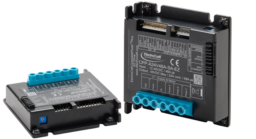
CPP-A06V48-EZ DC Motor Drives
CPP-A12V48-EZ DC Motor Drives
CPP-A24V48-EZ DC Motor Drives
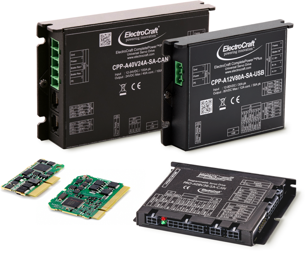
Universal DC Servo Motor Drives
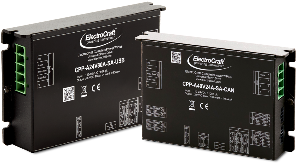
CPP-B06V48 DC Motor Drives
CPP-A06V48 DC Motor Drives
CPP-A12V80 DC Motor Drives
CPP-A24V80 DC Motor Drives
CPP-A40V24 DC Motor Drives
PRO Series Programmable DC Motor Drives
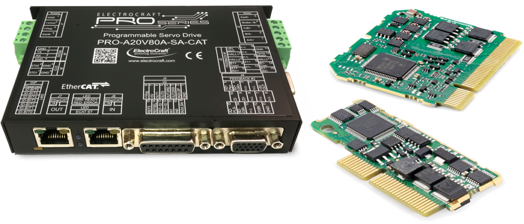
The PRO Series is ElectroCraft’s most advanced, high-performance drive platform with built-in programmable motion control, compatible with Brushless DC Motors, PMDC Brush Motors, and Hybrid Stepper Motors. The PRO Series embeds a sophisticated motion controller and drive into a single unit, allowing intelligent control by executing motion profiles stored in non-volatile memory. The PRO Series can also be configured as an intelligent slave, executing motion sequences received via CAN bus, EtherCAT or RS-232.
The PRO Series includes powerful setup, configuration, and programming tools with ElectroCraft’s MotionPRO Suite, Windows-based software.
more ▸The PRO Series can tackle a wide range of motion control applications from simple to complex and is available in multiple sizes and configurations, including chassis mount enclosures or PCB assemblies. Check out the full list of features in our downloadable PDF data sheet
◂ less